
Industrial Leak Testing: Measurement Methods and Technology
By industrial air leak testing we mean the set of procedures necessary to verify and measure the pneumatic tightness of manufactured components. In particular, this document is addressed to technicians responsible for end-of-line testing of mass-produced products.
Historically, the industries most equipped in this production phase have been those manufacturing articles with high intrinsic hazard, or with high technological value. Therefore, we can outline a first “generation” of production sectors where the sensitivity of this process has been felt from the beginning:
- Aerospace
- Mechanical
- Automotive
- Medical
- Appliances
- Hydraulic
- Electronics
- Packaging
- Foundry
- Pneumatic
- Gas
- Heating
Only around the late 1980s and early 1990s did a campaign begin to extend such testing to a wider range of products. It was indeed around this period that people started to understand that this type of testing could be extended with countless benefits even to products that are not dangerous in case of leakage.
If, for example, small oil leaks in engines or mechanical transmissions were considered acceptable in the 1970s and 1980s, from the 1990s onwards a small defect of this type already meant non-conformity for the end customer.
By applying this principle of technical availability at relatively contained times and costs, this testing methodology has expanded, and continues to expand.
Therefore, to date it is not possible to compile a complete list of industries where such testing is considered “necessary” and it can be generalized that any product capable of containing gases or liquids can benefit from such leak testing.
New to the concept? Read our guide → [What Is a Leak Test?]
Air systems
Industrial automatic pressure testing systems create a pressure differential or pressure difference between the area considered hermetic and the outside of the body to be tested. Each system can perform this test with methodologies.
Both systems execute a test cycle based on three fundamental phases:
- Filling, to pressurize the cavity under test
- Settling to stabilize the volume of air introduced
- Testing where the pressure trend is analyzed in order to measure any decay over time
Four methods are essentially known for Δp/Δt type measurement:
Absolute Systems
Absolute Systems
The absolute pressure decay system is the most immediate, economical and evident theoretical method to perform pressure drop measurement. ForTest’s T8990 is the equipment for industrial testing designed to perform pressure tests using the absolute pressure drop system. For further details, please refer to the technical data sheet.
The measurement system involves measuring the pressure drop inside the component under test during the testing phase.
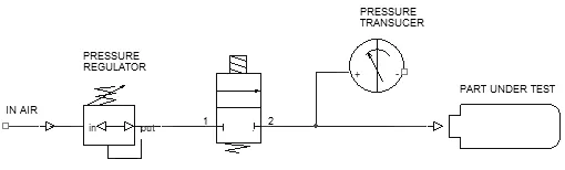
Analyzing the sketch, we will have that any pneumatic defect can be traced back to a leak, therefore to a rejection indication. For this reason, this system is defined as “fail-safe“.
The only risk element in this pneumatic circuit is represented by a potential leakage of the filling valve. This problem, which is also present in many pneumatic schemes discussed, can be easily prevented thanks to a particular set of valves replacing the simple valve shown in the scheme, and thanks to specific software diagnostics. On the other hand, the overall precision of this type of equipment is essentially related to the precision of the measurement section (transducer) and the electronic acquisition section.
In practice, the elements that limit precision are the electrical noise of the circuitry and the mechanical noise of the transducer, which correspond to the resolution or maximum number of points within which the full scale measurement is divided: a system capable of guaranteeing 100,000 points, on a full scale of (e.g.) 1 bar, corresponds to being able to guarantee a measurement resolution of one hundredth of mbar.
The higher this resolution parameter, the shorter the time required for decay measurement; this corresponds on one hand to a reduction in test cycle time, but more importantly to a containment of errors due to thermal variances of the gas introduced into the part.
The electronic strategies for achieving such results are of various nature: they range from driving the transducer with alternating voltages and using sophisticated AD converters to utilizing appropriate zero tracking circuits and windowed measurements, but above all, extensive filtering both electrical and mathematical of the measurement. Particular attention must be paid to determining the “zero” point of the pressure drop, and in practice to measuring the pressure at the initial moment of the test phase.
Differential systems
Differential systems
Thedifferential system is currently used in cases where it is necessary to have the same sensitivity at very different pressures, or where high-pressure tests are performed (>20 Bar), although we will see later that interception systems are still improved and safe given the high pressures involved. T8060 by ForTest is the equipment designed for pressure leak testing with the differential system. For more details, please refer to the technical datasheet.
Leak measurement through differential circuits represented until the 1980s one of the most ingenious pneumatic techniques in this field to overcome the poor precision of electronic measurements and data acquisition available until that time.
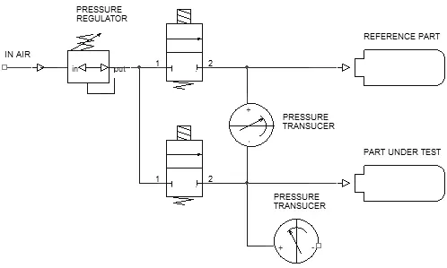
The system included, as shown in Fig.2, a double branch: on one side the part to be tested and on the other an identical but hermetic piece.
In practice, analyzing the scheme, the tests were carried out with the following logic:
- The filling phase was performed by commanding the opening of both valves
- The settling phase occurred with valve B closed and valve A open, in order to stabilize and equalize the pressure conditions in both branches
- Once the settling was completed, all valves were closed
Imagining the pressure transducer as a membrane (but the experience can also be replicated with a simple double-spout mercury column) we will have that at equilibrium the differential pressure is zero. Any drop in the test piece shifts the zero of this measurement allowing a very sensitive indication of such deviation. Based on this principle it is possible to perform easy electrical amplification of the signal coming from the transducer, and display it on a needle instrument with central zero. Therefore with this stratagem it was possible to analyze a typical drop value equal to 1/50,000 (transducers permitting) of the filling pressure value, while the electronics of that time, if applied in a manometric system did not allow exceeding the ratio of 1/10,000.
It became evident that the limit was solely that of the electronic measurement in terms of resolution and noise, because the operating conditions of the measurement transducer still had the limitations of a monometric system. Such transducer had to be dimensioned for the maximum filling pressure in any case, since besides being actually present in common mode, in case of leakage of the test part the diaphragm was stressed by the full pressure.
However, the pneumatic system thus realized presented several disadvantages: The first, and very evident one, is that the comparison examines a hermetic reference: a leak in such reference coincides with a “masking” of the actual leak measurement of the test piece. This defect was however partially compensable with continuous verification of the system in use through a “good” sample and electrical calibration of the measurement “Zero”. This first point classifies such pneumatic system as not “fail-safe”. The other most evident and felt disadvantages were the difficult calibration of the differential transducer measurement, which had to be performed with a particular verification procedure. But the real weak point of such system arose from the very nature of the plant: the leak measurement performed turns out to be a measurement that does not indicate the actual leak of the tested piece, but the relative difference with the sample.
This does not necessarily coincide with the concept that the reference sample may leak (which, incidentally, corresponds to reality). For example, consider that in the practical use of such systems, the sample part is mechanically stressed at every test cycle, while the part under test is stressed only during its own testing phase. In practice, a progressive trend of the measured pressure drop over the equipment’s operating hours will be analyzed, indicating the progressive mechanical settling of the reference sample that does not coincide with the settling of the parts under test. Furthermore, while there could apparently be benefits in terms of thermal variance due to the common mode, in reality the overall volume involved is doubled, and although the two elements being measured could be positioned close to each other, air currents or solar rays could amplify their thermal difference. In summary, this principle allowed remarkable results to be achieved until the 1970s and part of the 1980s, but today it finds no practical applications, as it has been superseded by the easier and more precise absolute pressure drop manometric systems.
The limitations of this system are:
- Higher pneumatic complexity
- Non-fail-safe pneumatics
- Dual pressure measurement section (filling and testing)
- Lower measurement repeatability
- Longer test times
- Higher equipment cost
Per comprendere le differenze tra il sistema assolutoo e differenziale analizziamo la figura 2 e considerando l’applicazione del differenziale in modo simmetrico, cioé con un pezzo ermetico campione e un pezzo in test;é facile capire che tra il primo collaudo della giornata e i successivi avremo che il pezzo campione avrá un cumulo d’assestamento sia termico sia meccanico pari a “n” mentre il pezzo in prova pari a 0, perché sostituito test dopo test.
To understand the differences between the absolute and differential system, let’s analyze figure 2 and consider the application of the differential in a symmetrical way, that is with a hermetic sample part and a test part; it is easy to understand that between the first test of the day and the subsequent ones we will have that the sample part will have a thermal and mechanical settling accumulation equal to “n” while the test part equal to 0, because it is replaced test after test.
Depending on the parts under test, whether they are used symmetrically or not, and the settling times, consider a ratio from 1:0.8 to 1:0.1 between absolute measurement and differential measurement: in other words, the mBar per second measured by an absolute or gauge system can be viewed as 0.8 – 0.1 mb/s in a differential system.
This does not mean that the differential system is not working properly, but simply that they are two different measurements, and this must be considered during installation.
Flow rate systems
Flow rate systems
The flow system allows for direct measurement of the air flow or flux generated by the leak. Upon completion of the filling and settling phases, the test time is the time required to obtain a stable measurement of such flow, which is generally very brief (e.g., 100..300 milliseconds). T8720 by ForTest is the equipment for industrial testing designed to perform pressure tests with the flow system.
For more details, please refer to the equipment technical datasheet.
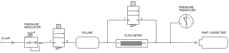
As shown in Fig. 3, the measurement of this flow is entrusted to a differential transducer capable of reading the pressure drop across a pressure loss.
In order to reduce the quadratic trend caused by the turbulence of gas particle motion, a laminar element capable of partially linearizing this function (Δp/Flow rate) is used.
For further information, reference can also be made to the CNR-UNI 10023 standard. As an alternative to flow measurement performed volumetrically (specifically with Δp measurement), the application of mass flow meters has gained greater prominence in the last decade, for example thermal systems or flow meters (“hot wire” systems), because they are more accurate, consistent over time, easily available in various scales, and less sensitive to thermal variance of the gas being measured. Considered a “historical” system for leak testing, leak testing measurements performed with this principle are distinguished by the following benefits:
This aspect is the real reason why this principle is still applied industrially. Natively, that is without artifices, with this system it is possible to analyze the leak for a determined time, allowing the operator to search for it and repair it in real time during the measurement.
As already mentioned, flow measurement being a continuous type of measurement, allows for the elimination of an actual test time. This concept, as we will see later, should be considered in a purely theoretical way, because while in pressure decay or Δp systems the settling or test phases can be partially overlapped, in this method the measurement must necessarily take place under the best settling conditions.
We consider this characteristic among the benefits, even though we will later analyze systems capable of performing the same measurement in a more precise and safe manner. Conversely, if compared to other systems, this principle presents some disadvantages; The first, and most evident, arises from the complexity and instability of flow measurement.
- Continuous Leak Measurement
- Test Phase Duration Practically Zero
- Leak Indication in Volumetric Units (CC/time)
In addition to the cost of a double measurement (pressure and flow) and therefore a double verification to obtain overall measurement validation, the laminar element which practically presents itself as a capillary is strongly influenced by dirt or deformations.
Therefore, the measurement must be constantly verified with reference nozzles, which in turn, appearing as micro-holes on a ceramic or metallic base, tend to deteriorate and thus have a limited lifespan. Furthermore, with particular reference to the sketch in Fig. 3, any parasitic leak upstream of the flow measurement element can falsify and mask any potential leak in the test piece.
Such pneumatic circuit cannot be considered fully “fail-safe”, and must be constantly verified. Finally, the sensitivity of the measurement is limited by the scale of the flow meter, while in pressure decay or Δp systems this limit, although present, can still be mediated by extending the test time.
The practical application of this leak testing equipment occurs fundamentally in four cases:
- When the volume of the component is unknown and variable: for example, engines on the oil side, very elastic bags or bottles;
- When testing times must be reduced to the minimum;
- When continuous measurement of the leak is needed to perform analysis and repairs;
- When the leaks to be measured are so high that a Δp system cannot maintain constant test pressure, distorting the leak calculation: cartridge valves or oil distributors, general leakages.
Normally for other industrial applications, Δp systems are more economical and durable, having fewer wearable pneumatic parts.