
Leak Testing
Leak testing refers to a procedure capable of verifying the pneumatic tightness of a component. Unlike most types of measurement, such as weight or dimensional measurements, leak testing almost necessarily requires equipment.
First of all, we distinguish two types of equipment for leak testing:
- A) sistemi di verifica, genericamente presidiati da operatore, con localizzazione della perdita:
- Water testing with pressurized part (visual inspection)
- Soap testing with pressurized part (visual inspection)
- Testing with pressurized reagents and ultraviolet lamps (visual inspection)
- Testing with pressurized gas (Helium) (mass spectrometer inspection)
- Hot air testing (infrared visual inspection)
- Dielectric variation testing on plastic parts (high voltage ionic system)
- Hydrogen gas testing (probe inspection)
- B) sistemi di tenuta automatici con indicazione di Buono , Scarto e valore di perdita :
- Measurement through flow rate measurement of the pressurized part
- Measurement through differential pressure drop between test part and sample reference
- Measurement through pressure drop of the pressurized part “Interception”
- Measurement of pressure increase in bell jar
While the first class of equipment (A) represents an irreplaceable area for statistical and off-line testing control, allowing the detection of very small leaks and analyzing defects directly in a visual way, type (B) instrumentation represents the actual “barrier” or end-of-line filter concerning non-compliant production.
Automatic leak testing systems (B) also allow monitoring of potential quality drifts over time, if applied throughout the entire production. Given the clear evidence of the operating principles of type (A) measurement systems, we will not dwell on a detailed technical description.
It should only be considered that systems based on mass spectrometers (“helium sniffers”), although expensive both in terms of equipment and management, are positioned at the top of sensitivity in terms of detectable leakage compared to any other system described in this document. Conversely, systems using water, soap or reagents, while allowing the determination of very small leaks at negligible operating costs, cannot be automated and therefore necessarily require visual inspection, and thus judgment by an operator.
From here on, the operating principles of Type B systems will be examined.
The selection of the appropriate testing method generally depends on the following parameters:
- Allowable leak rate value
- Type of test: leak localization or leak measurement
- Specifications of the part to be tested: dimensions, pressure or vacuum resistance limit, assembly materials, surface finish etc.
- Operating and testing conditions
- Safety and environmental parameters
Some of the applicable methods are shown in the following table:
| Metodo | Gas | Tipo di prova | Sensibilità [ Pa m³/Sec] |
|---|---|---|---|
| Gas traccianti e Spettrometro | Elio | Local./ Pass-No Pass | 10-11 ... 10-6 |
| Prova di intercettazione compliance in campana | Aria | Pass-No Pass | 10-6 |
| Prova per calo di pressione | Aria | Pass-No Pass | 10-5 |
| Prova per portata Volumetrica o di Massa | Aria | Pass-No Pass | 10-4 |
| Prova visiva in vasca d'acqua e aria in pressione | Aria | Pass-No Pass | 10-4 |
The Helium method is not taken into consideration as it is not included in our production. It should be noted that this system ranks at the top in terms of sensitivity, and the installation and management costs make it applicable only where truly necessary, namely in the field of refrigerant gas components, microelectronics, pacemakers, etc.
The immersion test is also not mentioned here since it has no technical value other than being able to actually see the leak point and locate it. The low sensitivity level defined by the standard must, in fact, be interpreted as the method’s inability to provide a measurement, overall uncertainty if applied in production lines, and high management costs due to the impossibility of being automated.
Testing phases
As an introduction to a detailed description of the various types of automatic equipment for pressure leak testing, it is necessary to define some characteristics common to the various operating principles. Each system described has in common the need to create a pressure differential or difference between the area considered hermetic and the outside of that body. This phase is called the filling phase.
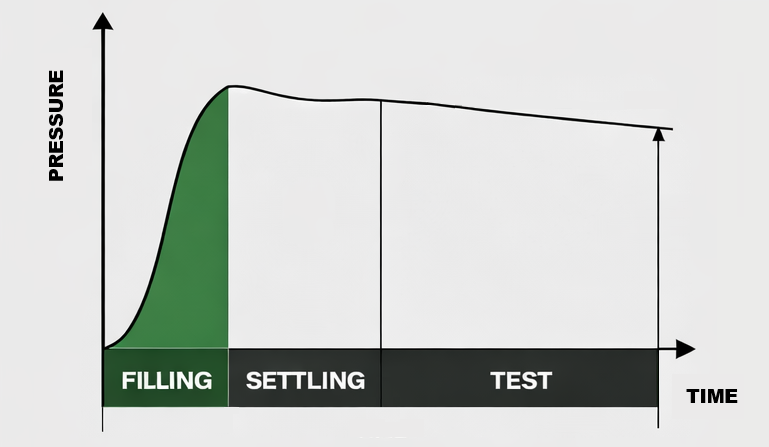
In principle, the filling can be performed with both positive and negative pressures, and with pressure (or vacuum) applied from either inside or outside the test piece. Following this phase, there will be a stabilization phase, necessary to stabilize the pressure or flow values for the leak measurement.
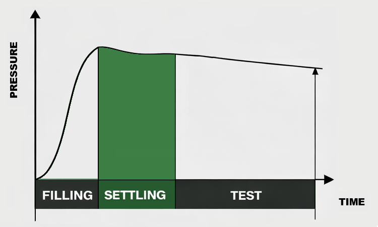
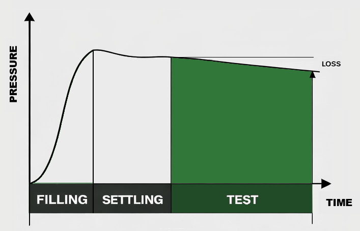
Only after completing these two phases will we have the execution of the actual leak measurement, using the various strategies that we will analyze in detail. For clarification purposes, we present a graph showing a typical pressure trend during the execution of a manometric leak testing (pressure drop).
The filling strategy, therefore whether from inside the part (most common case) or from outside (bell jar), the type of filling, i.e., pressure or vacuum, and the value of such pressurization, must be chosen case by case by analyzing the particular part to be tested. For this choice, the first parameter to address is the pressure value to be used to perform the filling, and therefore the test.
Considering the use of common industrial compressed air, this value can typically range between -1 bar and 10 bar in most common cases, and in the case of leak testing combined with burst or explosion tests, this value can reach even beyond 40 bar.
Contrary to what one might intuitively assume, using high pressure values worsens the overall performance of the tests because, while on one hand the measured leak value is proportionally increased, which is anyway proportional to the scale of pressure or flow measurements, the use of high pressures complicates the progress of the filling phase and the subsequent stabilization or settling phases.
Therefore, and in principle, tests and filling operations performed at low pressure (less than 1 bar) should be preferred. The use of vacuum filling can, for example, improve the sealing of the part during testing phases. In the case of containers or parts with large “open” sections, such as engine oil “cups” or crankcase half-shells, a simple soft rubber base is sufficient to make the part hermetic, without the need to apply excessive counteracting forces. However, vacuum filling can be misleading in the case of leak testing on welded plastic parts, since the vacuum tends to cause the defective weld to collapse and therefore “stick together”. In such cases of welded plastic parts, high pressure helps to expand any defect; therefore, testing performed at pressure between 3 and 8 bar combines leak testing with a potential robustness test of the welds.
Particular attention must be paid when the part under test consists of “non-linear” sealing mechanisms such as valves or spring-loaded flaps, and the tests must be performed either at a pressure much lower or much higher than the operating point of such valves. On mechanical parts such as cast iron crankcases of engines or transmissions, the presence or absence of seals or components guaranteed up to a known pressure must always be considered. Test specifications for gas and kitchen appliance parts indicate leaks at low pressures, typically 150 mbar. An important note concerns those metallic parts that exhibit expansion behavior after pressurized filling.
Such components, including coils, heat exchangers, etc., tend to expand mechanically at the end of filling, progressively according to the applied pressure. Considering cases where such elements must necessarily be tested at relatively high pressures (4.7 bar), and where such expansion cannot be compensated by the settling phase except with prohibitively long times, the use of pre-filling to a value higher than the test value allows excellent expansion/relaxation results, drastically reducing the overall test time. In summary, the choice of pressure value at which to perform the tests must reflect on one hand the actual operating pressure of the component, considering case by case the benefits and disadvantages of various pressure levels.
The choice of a “bell” filling, and therefore from the outside of the part, generally in depression, is discussed later in a dedicated paragraph. Common to every type of filling is the gas used, which in the majority of cases is compressed air. This air is intended to be filtered, obviously free of oil, and dehumidified as much as possible. If industrial air from a general-purpose circuit is used, the application of a local cylinder or expansion vessel to the test equipment improves the temperature variance characteristics between air and part.
Alternatively to air, gases with smaller atom dimensions can be used, such as helium, since they increase leak flow and enhance test sensitivity. Finally, it is necessary to consider the use of inert gases such as nitrogen, in case of testing components already treated with explosive or flammable elements, such as leak testing on automotive fuel lines or fuel components in general.
Leak rate analysis
“Zero” leakage does not exist and even if it did, it would not be possible to measure it. Therefore, based on tables provided by regulations, it is always advisable to define in advance the acceptable leakage level for your specific part.
After this initial evaluation, it is necessary to study the working fluid (gaseous or liquid) and the operating pressures to which the component to be tested is subjected.
In the case of gas components, where there is no “watershed” between the molecular dimensions of the fluids (test/operational), we adhere solely to hazard assessment: for example, the same gas component may have two completely different acceptable leakage levels depending on whether it is applied in a domestic environment (kitchen) or for outdoor transmission lines.
Examples of leak rates established by regulations for gas components are:
- 15 – 60 nCC/hour @ 150mBar : for kitchen gas manifolds
- 1 – 5 nCC/minute @ 5 Bar : for outdoor gas transmission line joints
In the case of gas components, where there is no “watershed” between the molecular dimensions of the fluids (test/operational), we adhere solely to hazard assessment: for example, the same gas component may have two completely different acceptable leakage levels depending on whether it is applied in a domestic environment (kitchen) or for outdoor transmission lines.
Examples of leak rates established by regulations for gas components are:
- 0.3 – 0.6 nCC/Minute: for fuel containers
- 2.0 – 3.0 nCC/Minute: for water containers
- 3.0 – 6.0 nCC/Minute: for oil containers
In reality, where possible, it is better to apply higher pressures, within the range of 1..6 Bar maximum. With this solution, testing times can be reduced and the performance of the test can be significantly improved. Increasing the test pressure results in an amplification of the leak, which is generally not linear to the pressure: if for example we measure 1 nCC/minute at 1 Bar test pressure, the same leak measured at 5 Bar may result in much greater than 5 nCC/minute.
Furthermore, higher pressure amplifies any potential defect, if elastic, by widening the opening as in the case of plastic welds or cracks.
On the contrary, it is necessary to evaluate the negative aspects of higher pressures, such as longer settling times in the case of elastic components, “masked” leaks in the case of lip seals for example, where high pressure increases the sealing of a defective part, and safety issues for people and the surrounding environment. Therefore, the right test pressures must be sought in collaboration with industry professionals who have years of experience and, above all, the equipment to perform all the necessary initial tests.
Relationship between leakage rate in vol/t and ΔP
We want to formulate the relationship between leak rate expressed in vol/t (e.g.: cc/min, cc/h, etc.) and pressure drop inside a part during absolute pressure drop leak testing.
Starting from the ideal gas formula: 𝑃𝑉 = 𝑛𝑅𝑇 Where we assume:
P = filling pressure of the part under test
V = volume of the part
n = number of moles inside the part
R = universal gas constant
T = temperature
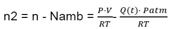
After “t” seconds, due to a leak that we will call “Q”, we will have a number of moles dispersed in the environment equal to:
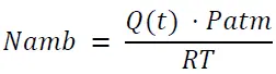
The remaining moles inside the volume will therefore be:
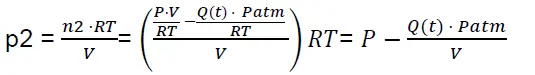
Assuming constant temperature, after a time t we will have this pressure inside the part:
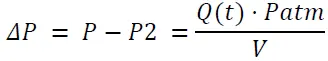
Therefore, defining the pressure drop ΔP as P – P2, we have that:
Solving for Q we get:
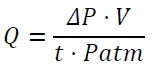
Which is the theoretical leak derived from a pressure drop inside the part in “t” time. In this analysis it is necessary to assume that pressure and temperature remain constant during the test time “t”.
Calibrations and verifications
We conceptually distinguish periodic calibration from routine checks as two distinct processes:
Calibration refers to a procedure intended to verify the overall functioning of the equipment in terms of compliance with the declared limits of precision of the electronic measurement and pneumatic operation.
Routine verification is performed at predefined intervals and is intended to check the equipment within the limits of normal use, and therefore verify its Good and Reject indication by applying respectively a sample designated for such testing that is hermetic and one with a known leak.
Both processes must be performed at predetermined time intervals. Analyzing various specifications or standards related to these procedures reveals that no universally applicable data exists.
The M2710 is ForTest’s ideal portable digital calibrator for performing calibrations on leak testing equipment for industrial testing.
For more information, please refer to the technical datasheet.
The typical interval for calibration operations can be estimated at 6 or 12 months. The typical interval for routine verification operations can be determined by the number of parts produced and approximately at intervals equal to 25% of daily production.
This calibration essentially serves to set the zero and full scale of the absolute pressure measurement, and, where required and in any case only for verification purposes, the measurement of pressure drop during a test. The approach is therefore similar for executing a sample with controlled leakage.